
![]()
![]()
![]()
![]()
![]()
![]()
![]()
|
For The Agency | For The Technology Developer | For The Magazine Publisher | For The Individual |
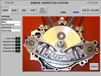
Vision System Keeps Engine Production MovingWhat started out as a simple pass-fail test system ended up performing over thirty automated inspections. The following is a manuscript for an article published in Vision Systems Design magazine. Vision Systems Design magazine holds the copyright for the finished article. by C.G Masi, Contributing Editor When Milwaukee, Wisc. motorcycle manufacturer Harley Davidson approached Scott Woida, President of Midwest Engineering Systems in West Allis, Wisc. to design a system that would verify the correct timing-chain installation in their new Twin-Cam 88 engines, they only envisioned making the one pass-fail inspection. "As soon as Harley learned that we were considering a vision system to do this," Scott recalls, "they started to say: 'Well, maybe we could also ensure that the washers are put on correctly, and the sprockets are tightened down all the way. Then, we could see that the guides are pressed down completely. As long as we are looking at these things that span the entire engine, let's look at all this stuff!' "So, we ended up performing 30 some-odd inspections on the engine." To make it run more smoothly than their previous engines, Harley had designed the new motor with two balance shafts installed parallel to the crankshaft. One balance shaft is ahead of the crankshaft to drive the intake and exhaust valves for the front cylinder. The other is behind the crankshaft to drive the rear-cylinder valves (See Fig. 1). A timing chain running over sprockets on the three shafts keeps them turning in synchrony.
The original timing-chain inspection was needed to ensure that the timing chain was installed correctly so that the intake and exhaust valves would open and close at the proper time with respect to the crankshaft's rotation. When the timing chain is installed correctly, marks cast into the sprockets line up with discolored links in the timing chain, as Fig. 2 shows.
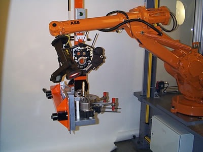
This is quite an easy task for a machine-vision-based inspection system to perform. Additional inspection tasks that involve verifying the presence of all the components that should have been installed by this point in the assembly process are also fairly simple for an automated inspection system. When Harley asked that the vision system be able to verify that certain components were properly tightened, however, things became more difficult. For example, there are two spring-loaded chain tensioners visible in Fig. 1. To ensure proper chain tension, the tensioners have to be rammed all the way down in their sockets. The vision system can verify that they were rammed all the way home by measuring the distance from the casting surface to the top of the chain-tensioner body. Making that measurement, however, requires precise positioning of the camera with respect to the target. Precisely positioning the camera is complicated by the fact that the engines are carried through the assembly area on J-hooks, which are approximately 12 feet (4 m) long, suspended from an overhead conveyor. These J-hooks can only be relied on to position the engine in the inspection cell to within +/- 2 inches (5 cm) in x, y, and z, and several degrees rotation around the vertical (z) axis. Later, Midwest engineers realized that there was also a large planarity error as well. That is, engines do not always sit flat on the J-hook, so the plane in which the timing chain runs can not be relied on to line up with the x, y (horizontal) plane. System Architecture The engineers' first idea was to use a mechanical fixture to position the engine under inspection with respect to several cameras. They soon realized, however, that they could make a more robust, flexible system that was faster and easier to use by mounting a single camera on a five-axis robot arm as shown in Fig. 3.
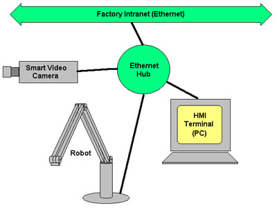
Fig. 4 shows the system they came up with. The camera is a Series 600 SmartImage Sensor from DVT in Atlanta, Ga., which incorporates a sophisticated image-processing system in the camera body. The robot is a Model 1400 robot manufactured by ABB in New Berlin, Wisc. The HMI (human-machine interface) terminal is a desktop PC running software the engineers wrote to communicate with the other system components. The system components communicate with each other by being nodes on an Ethernet network, which also communicates with the factorywide intranet.
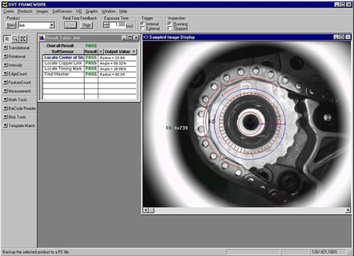
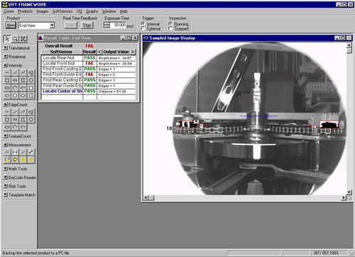
The robot's internal computer controls the inspection process. It knows which inspections should be done in what order. The SmartSensor camera, on the other hand, knows how to do the inspection. Its internal computer is configured with all of the image-processing routines needed, and programmed with the particular image analysis procedure needed for each inspection. Woida divides the procedures into two classes: orientations and inspections. Orientations are visual-feedback-directed robot motions used to move the camera to the precise location and orientation to capture the image needed. An inspection is the capture and analysis of that image. Inspections are generally done in groups of up to six. Thus, the system might perform an orientation to capture the image in Fig. 5, where the camera is looking the timing chain edge on. The camera captures the image and performs its group of inspections. These may include determining whether the sprockets have been tightened down (shown) and whether the chain is aligned with the horizontal plane. The camera's internal computer then sends an Ethernet packet through the Ethernet hub to the HMI interface to inform the operator whether the unit passes. The packet is formatted to carry results of up to six tests.
If any of the tests fail, the camera also sends a failed-image file, which is stored in a database on the PC. Then, the system goes on to complete the rest of the inspection sequence to find any other failures. After finishing the entire inspection sequence, the PC tells the operator whether the unit passes or, if there has been one or more failures, what corrective action to take. There are 20 seconds built into the 80 seconds each engine spends at this inspection station to allow repairs. Using Ethernet to tie the system components together has a number of advantages. Installation and cabling is much simpler than it would be using other interconnection protocols. Each component (smart camera, PC and robot) has its own IP address, so intra-system communication can use standard network protocols and software. Finally, Ethernet allows seamless integration into the factory wide network, so the inspection system does not become an island of automation apart from the factory management system. "I can sit anywhere in the plant and monitor that camera," says Woida. "I can see what it's seeing. If I have the correct access and security, I can actually program that camera from anywhere on the network." Making It Work Lighting, of course, is one of the most critical elements of any inspection system development. The inspection cell itself is curtained off to control lighting variations as well as to prevent human intrusion into the space while the robot is operating. Three lighting sources are used. First, area floodlights provide bright, even illumination throughout the cell. The SmartSensor camera comes with a high-intensity LED light source mounted on its body, which the inspection system uses at the start of the inspection sequence, when it is first trying to locate the engine in the cell. Finally, when the camera gets in so close that its body may block the area lighting, a ring light mounted around the lens floods the visual field with even illumination. The inspection sequence starts with the robot well away from the J-hook carrying the engine to be inspected. Supposedly, the J-hook is locked into a certain orientation, carries the engine laying flat on its side (with the crankshaft pointed vertically), and stops in a certain spot. Any of those assumptions, however, could be wrong. The inspection system, therefore, has to start by checking to make sure it isn't going to damage itself by bumping into the engine or the hook. From that rough evaluation of the scene, it can determine where it should start maneuvering. All of the orientation procedures are designed as feedback loops. To locate itself with respect to the engine in the x, y plane, for example, the camera takes an overhead image of the engine. The camera's image processor locates the crankshaft end and calculates how far it appears from the image center. The processor then sends a two-dimensional displacement vector over the Ethernet to the robot, which moves the camera. The camera then takes another image and sends a correction back to the robot, which moves the camera again. The feedback loop keeps going until the displacement error falls within a preset tolerance. Once the camera is centered over the crankshaft end, the system uses a second feedback loop to rotate itself into q-alignment using a second feature to determine the required rotation angle at each step. To locate itself in the z direction, the system locates a certain machined hole in the engine case that has a known diameter. The image processor measures the hole's diameter (in pixels) at the image plane, compares that with a target apparent diameter, and estimates how far to move the camera toward or away from the engine to achieve that target. That estimate then goes to the robot, which moves the camera, and so forth until the apparent diameter comes within its tolerance. Finding the planarity error is the most complicated orientation procedure. To estimate the planarity error, the image processor measures the apparent diameters of three holes and uses solid trigonometry to calculate a correction, which will comprise a three-dimensional displacement and a j-angle correction. Again, the feedback loop continues until the correction magnitude falls below a tolerance. It took about a year from the time Harley Davidson first approached Midwest Engineering Services with the inspection problem to the time the first system was fully operational. The engineers spent about six months to analyzing the problem, developing a solution and building the system. Then, it took about four months to get it installed on the production floor-mostly because the installation had to be coordinated with Harley's annual Christmas shutdown. "Then," Woida recalls, "we sat on their floor for another two months and made all of those changes.... Such as where you watch 100 parts go by and make sure the system can handle all the different variations between the parts." There were two main difficulties the engineers had to overcome in this project: planarity errors and part variations. "Once we licked [the planarity] problem," Woida recalls, "most of our problems went away." Part variations arise from the fact that Harley uses multiple suppliers for many engine components. Harley's designers define the significant engineering specifications, but many properties are left to the suppliers' discretion. For example, the dimensions of a washer inside of the engine were defined, but the finish (which makes no difference to the engine's operation) was not. So, washers arrived with anything from a polished surface to a matte anodized finish. While that variation didn't make any difference to the engine, it gave the inspection system fits! For some variations, it was possible to open up the tolerances on what the vision system would accept. In other instances, such as the washer situation, Harley had to add a finish specification to their part requirements. "This was our initial [inspection system] project," Woida points out. "It was a learning experience. Since then, we have developed a piece of software that almost automates the creation of the inspection routine. There has been a lot less custom code that had to be written for subsequent versions." |
|
Home | About Us | Technology Journalism | Technology Trends Library | Online Resources | Contact Us For The Agency | For The Technology Developer | For The Magazine Publisher | For The Individual © , C. G. Masi Technology Communications, Privacy Policy P.O. Box 10640, 978 S. San Pedro Road, Golden Valley, AZ 86413, USA Phone: +1 928.565.4514, Fax: +1 928.565.4533, Email: cgmasi@cgmasi.com, Web: www.cgmasi.com Developed by Telesian Technology Inc. |