
![]()
![]()
![]()
![]()
![]()
![]()
![]()
|
For The Agency | For The Technology Developer | For The Magazine Publisher | For The Individual |
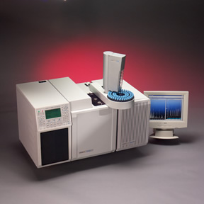
Instrumentation Needs Drive Turbopump DevelopmentRapidly increasing demand for chemical-analysis instruments--especially various forms of mass spectroscopy--is pushing vacuum pump makers to produce cleaner, smaller, and smarter turbopumps. The following is a manuscript for an article published in R&D magazine. R&D magazine holds the copyright for the finished article. C.G. Masi, Contributing Editor "The driver right now," says Joe Fabrizio, Director, Marketing for Instrumentation, Leybold Vacuum U.S.A., Export, Pennsylvania, "is really drug discovery." The vehicle Fabrizio refers to being driven is turbopump technology. Turbopumps (more properly called turbomolecular vacuum pumps) are provide the operating conditions for equipment in a wide variety of industries, including semiconductor, aerospace, chemical & petrochemical, optical and, as Fabrizio points out, pharmaceutical. While a great many of these applications--representing a huge volume of turbopump sales--do not involve analytical instrumentation, what Fabrizio is telling us is that the pressure point for turbopump technological development right now is in the analytical instrument area, and specifically analytical instruments serving the drug discovery and pharmaceuticals industry. That is not surprising because the pharmaceuticals industry is undergoing a major technological upheaval. "What they used to do," Fabrizio recalls, "is they'd hire a bunch of Ph.D.s and throw them in a room, then, [those chemists] would come out five years later with a drug. "What they do now is they start with a general direction to go in, then pay some guy or a lady eight bucks an hour to use really fast instruments to run a million samples. They then use sophisticated computer software to analyze the results of running those million samples. Out of the million samples, perhaps 100,000 look promising, so they do more in-depth experiments on those 100,000 samples. They reduce and reduce until finally they come up with 500 really promising compounds. Then they give those 500 compounds to the 50 Ph.D.s!" The instruments used to analyze those millions of samples are increasingly often automated GC- or LC-MS (see Table 1) systems such as that shown in Fig. A. While just about every kind of mass spectroscopy, from quadrupole to time-of-flight, is represented, they all rely on turbomolecular pumps to create the conditions under which they can work.
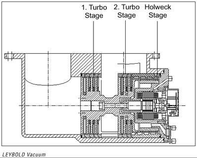
It's no wonder that the bulk of the new-sales volume for turbopumps comes from this industry. Considering that the analytical instruments into which those pumps go are undergoing a major technological revolution as well, it is no wonder that these applications are providing turbopump manufacturers with major design challenges. Turbopumped Instrumentation "Vacuum is not a product," Bill Foley, Marketing Director at for Varian Vacuum Technologies in Lexington, Massachusetts points out. "Vacuum is a condition. It's a state that the equipment has to be in to provide sensitivity, accuracy, and repeatability." Turbomolecular pumps are a popular means of producing that vacuum condition because they are clean, rugged, easy to use and relatively maintenance free. As Fig. D shows, the classic turbomolecular pump consists of several stages of what look like fan blades. While they can function like fan blades at atmospheric pressure or low vacuum, in the high-vacuum regime where they do most of their work, they actually behave more like cricket bats or ping-pong paddles to deflect individual gas molecules toward the outlet (or "high pressure") end of the pump, where they must be removed from the system by a backing, or forevacuum, pump.
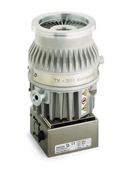
As Fig. B shows, useful turbopumps consist of a rotor carrying multiple sets of blades rotating at high speed (several tens of thousands of RPM) separated by sets of stationary blades. Each rotating set followed by the corresponding stationary set is called a stage. The stationary blades re-direct the swirling motion molecules pick up from their collisions with the previous set of rotating blades into a direction that makes collisions with the next set of rotating blades more effective.
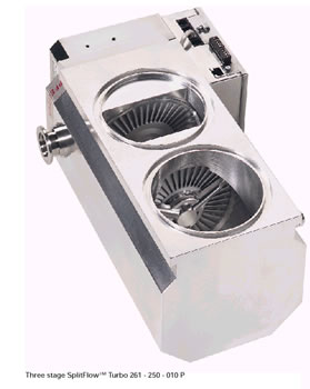
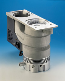
Many modern turbopumps follow the fan-like stages with a Holweck drag-pump stage. The Holweck pump uses viscous forces between a smooth cylindrical rotor and the gas (now at some-what higher pressure where viscosity is a useful concept) to drag the gas through spiral channels machined into a stator toward the turbopump's forevacuum end. "Typical turbo pumps exhaust in the middle Torr range," says Michael Sears, Marketing Manager, Analytical Instruments, Pfeiffer Vacuum, Nashua, N. H. "But if you combine a turbo pump and a drag pump, you get the high compression range [of a fan-type at low pressure], and you're able to exhaust at higher pressure." The ability to exhaust at high pressure allows you to pump more gas out of the system with the same forepump. The turbopump's ruggedness and versatility is due to this simple plan. Since the pump operates by mechanical action with only one moving part, it can be operated (and will even pump gas) at atmospheric pressure for short periods of time with no damage. Not surprisingly, different types of analytical instruments present different technical challenges to their turbopumps. "You have higher gas flows in MALDI-TOF than in LC-MS in general," Tench Forbes, Marketing Manager for the Instrumentation Market Segment for Europe and the Far East for Varian Vacuum Technologies, Turin, Italy explains. "You also have multiple-chamber instruments with TOF and LC-MS, whereas GC-MS typically uses one chamber." "Typically MALDI-TOF instruments are physically larger and also far more costly," Roseann Varvaro, Varian's Market Manager for Instrumentation in North America points out. "So they have different needs from GC-MS instruments, where cost and space are more important." "The vacuum system is one of the most important things in an MS system," Pheiffer's Sears opines. "It probably is the most expensive single component in the mass spec other than maybe the detector." Thus, cost is a major consideration in developing a turbopump for GC-MS applications, but it is less a concern (although still a consideration) in LC-MS applications, especially MALDI-TOF. One desirable characteristic of turbopumps destined for MS applications is throughput, or the volume (translated to standard temperature and pressure) of gas that moves through the system per second. "The more gas they can bring through," Sears points out, "the higher the resolution." Needs for achievable base pressure (that is, the minimum pressure the turbopump can achieve in the instrument under operating conditions) also vary from application to application. TOF instruments, which require gas ions to drift through a relatively long tube as part of the analysis, have fairly rigorous requirements for base pressure. IT-MS systems, which are much more compact (see Sidebar), are much more forgiving of high base pressure. In summary, the specific requirements for any given application are likely to be fairly unique to that application. Although trends are evident within various application groups, the vacuum system specifications are so intimately coupled to the design details of the system as a whole, that each application generally requires a more or less custom design. This sounds like a recipe for a lot of expensive one-off turbopump designs, but that is not necessarily the case. Remember that these pumps are OEM units designed and built to go into new models in an instrument manufacturer's product line. One reason there is so much interest in serving the pharmaceuticals market right now is that a pump designed for a successful product line can generate significant sales volumes over which to amortize the non-recurring engineering costs. The trick, of course, is to create a successful product. While there is no sure-fire recipe for success, one of the best ways to avoid disaster is to begin working with suppliers as early as possible. "We work on being involved up front with the system designers and giving them ideas on possible performance enhancements for their vacuum systems," Sears says. "We like to be involved, perhaps, a year ahead of the prototype phase. At that point, we can discuss the vacuum needs and the constraints on the vacuum system. "Our job is then to come in with suggestions. We would present one or several design possibilities for the turbo pump, the roughing pump, gauging and a variety of other things. Given advance notice, we can come in with a solution that allows them to take the next step in their system." Multi-Port Turbopumps As Varian's Forbes pointed out, many LC-MS instruments require different gas pressures at different locations within the machine. "They're going from a high pressure region," says Leybold's Fabrizio, "where they introduce a sample to be analyzed (at approximately one torr pressure) to the next section, which is normally between 10-2 and 10-4 torr. That is normally where they direct the ions toward the detector area. The detector is yet another chamber, which is usually in the 10-5 to 10-6 torr range." Standard practice has been to provide a separate pump for each of these sections. Only the first section is anywhere near the range at which forepumps operate. All are, however, solidly within turbopump country. So, this archetypical LC-MS application would call for three turbopumps operating at different base pressures and gas loads, along with the associated plumbing, control-lers, etc. That can get very expensive very fast, and it also will take up an awful lot of room. It also means a lot of moving parts, which can cause maintenance and downtime headaches for what Fabrizio calls "instrument foundries," which are large facilities with many, many such instruments dedicated to mass-processing of samples looking for drug candidates--prime customers for the analytical instrument makers who incorporate turbopumps into their products. Multi-port turbopumps, such as the one shown in Fig. E, are a much better alternative for these applications. These units provide two or more gas inlets that open into different pressure regions of the pump.
In any turbomolecular pump, gas enters the main inlet at the base pressure and is compressed as it passes through the stages in a serial fashion. So, if you need four different pressures in four different parts of your MS system, you can plumb the lowest pressure to the main inlet, where it will see the base pressure, then the next-highest-pressure chamber to an inlet a few stages farther on, the next higher pressure to a second intermediate level, and the roughest vacuum (highest pressure) chamber to, say, just before the Holweck drag-pump inlet, or even to the forevacuum line. By carefully selecting how far along the turbopump stack you provide the inlet for each chamber and adjusting the gas load let into each chamber, it is possible to tune the system to provide just the right pressure in each part of the MS system. The advantages of using a multi-port turbopump in such an application include lowering size, weight, and cost--just the things system designers want to minimize. Size and cost are lowered by providing all the system's pumping needs packaged into one housing containing one motor, one rotor and one set of electronics. The cost of that one pump, of course, is likely to be higher than the cost of a conventional turbopump of equivalent throughput and base pressure. It will, however, almost surely be considerably lower than two or more such equivalent pumps. Multiport turbopumps' disadvantage relative to installing a separate pump for each vacuum chamber is the plumbing challenge. It's easy to see the most effective plumbing scheme when you have a separate pump for each chamber--just hook the pump inlet as directly as possible into the chamber. It's not so simple when you have one unit serving several chambers. While the designers of the unit in Fig. E chose to use a relatively long shaft to put the pumping stages right where they are needed (minimizing the plumbing between each chamber and its inlet), the folks who designed the unit in Fig. G chose to use a somewhat longer high-vacuum line to bring gas into a more compact pump. These are the types of engineering judgements that need to be made to fit a turbopump exactly to its application.
Clean-Bearing Technology I mentioned "cleanliness" as being one of the turbopumps signal advantages. To a vacuum engineer, "clean" means not introducing extraneous volatile materials into the vacuum system. All materials, including plastics, glasses and even stainless steel, have a certain probability of vaporizing under vacuum conditions. The material's vapor pressure, which is a function of temperature, measures this tendency to evolve vapors. Obviously, plastics and other organics have much higher vapor pressures than stainless steel at any given temperature. Turbopumps' cleanliness stems from the fact that all the mechanical moving parts exposed to vacuum are made of aluminum or steel, which have negligible vapor pressure. The electrical components for the motor (and the concomitant organic plastic insulation materials) can be isolated outside the vacuum walls. The only source of contamination in a turbopump is in the bearings, making clean-bearing technology critically important. Materials normally used to lubricate sliding surfaces tend to be organic fluids or semifluids. They tend to have vapor pressures very near or even above atmospheric pressure at normal operating temperatures. This is why motor oil and grease "smell." If they didn't evaporate, you couldn't smell them. Extraneous volatile materials can cause difficulties for MS system in two ways. They can limit the system's base pressure and they can create spurious signals in the analysis. A quantity of volatile material (such as a stick of butter) placed in a vacuum chamber limits the system's base pressure to its own vapor pressure. As soon as the chamber pressure goes below the material's vapor pressure, the material begins evaporating, which pushes the chamber pressure back up. When the pump removes the vapor, the chamber pressure again attempts to fall below the material's vapor pressure, and more material evaporates. The process goes on as long as there is material in the chamber to evaporate. The pump, however, can't remove all the vaporized material. Some of the vapor condenses onto the chamber walls, like dew on grass, making the chamber's entire inside surface a reservoir of volatile molecules. Any attempt to pump the chamber to below the material's vapor pressure is therefore doomed to failure. Even if the material's vapor pressure is lower than the base pressure needed for the MS to operate properly, some molecules do evaporate. These molecules can and will become mixed with the analyte molecules you are studying, potentially introducing spurious signals into your results. Clearly, something must be done to keep contaminant molecules from backwashing into the MS system. Traditionally, turbopump manufacturers have gone to great lengths to
Two additional methods are now being employed in turbopumps intended for analytical-instrument applications: magnetic bearings and dry lubricants. Magnetic Bearings As any physicist or electrical engineer can tell you, it is impossible to create a stable levitation system using magnetic forces alone. If, however, you add an additional non-magnetic force, such stability can be achieved. By essentially squeezing the turbopump shaft between two magnetic bearings, engineers learned to use mechanical thrust to stabilize magnetic bearings for turbopumps decades ago. "Leybold came out with the first one in the mid seventies," Fabrizio recalls. "Unfortunately, there was no market." "It was in the semiconductor industry where the market for magnetic turbopump bearings really appeared. Truthfully, it's still limited to the semiconductor industry--to the people who can pay for it. Magnetic bearings are expensive, but the cost is insignificant compared to the cost of the rest of the tool." Magnetic bearings, however, have an obvious advantage as MS users strive for greater and greater measurement performance. Will turbopump users be willing to pay the added price for this level of cleanliness? Will turbopump manufacturers be able to bring the price down enough to close the cost/benefit gap? We shall see in the next few years. Dry Lubricants Another alternative is to eschew viscous-fluid lubricants in favor of dry lubricants. Manufacturers of magnetic data recording products, for example, have long used dry-lubricant technology to reduce friction between read/write heads and hard disk surfaces. That same technology can help improve turbopumps for analytical instrument applications. "The bearings in Varian ceramic-bearing turbopumps are permanently lubricated, so there's no external oil supply of any sort," Forbes points out. An additional benefit of this technology is that the pumps can be mounted at any orientation, horizontally or vertically. With no liquid lubricants, there is nothing to spill. Improved Controller Electronics Not surprisingly, the microelectronics revolution that has made itself felt everywhere else has also had its effect on the electronics needed to control turbopumps. Circuit miniaturization has made turbopump controllers tiny, and microprocessors have made them smart. "The controller is the brains of the turbopump," Pfeiffer's Sears points out. "You supply DC power and operation signals, and you have a fully functional system. It used to have to be mounted in a behemoth rack mount" "Instead," says Leybold's Fabrizio, "the controllers for the new pumps, especially for those intended for the analytical-instrument market, are little boxes that mount right on the pump. They are about two inches tall, four inches wide, four inches deep (5 cm x 10 cm x 10 cm)." Since they are generally intended for OEM applications where they are part of a computer-controlled automated system, they can also incorporate sophisticated internal diagnostics. For example, by monitoring the pump-motor's current draw, they can get advanced warning of developing failure conditions. Rising current draw means the motor is working harder. That can mean that, say, the bearings are going bad, or a vacuum problem is making the forevacuum rise. Coupled with other system measurements, such as the actual forevacuum pressure, this information can help the host computer monitor the whole system's health. "What the instrument manufacturers want to do," Fabrizio says, "is to make the instrument a black box--a no-brainer for anyone. So none of this functionality is exposed to the user. The user doesn't know anything about what is going on in the machine." All they have to think about is the Science that comes out. Table 1: Mass Spectroscopy Alphabet Soup
|
|
Home | About Us | Technology Journalism | Technology Trends Library | Online Resources | Contact Us For The Agency | For The Technology Developer | For The Magazine Publisher | For The Individual © , C. G. Masi Technology Communications, Privacy Policy P.O. Box 10640, 978 S. San Pedro Road, Golden Valley, AZ 86413, USA Phone: +1 928.565.4514, Fax: +1 928.565.4533, Email: cgmasi@cgmasi.com, Web: www.cgmasi.com Developed by Telesian Technology Inc. |